How to Draw Planar Tensile and Shear Stress
Engineers virtually often wants to make up one's mind the maximum normal stress induced at a given bespeak for a particular application or design.
Mohr's Circle is graphical tool that is commonly used past engineers to graphically clarify the principal and maximum shear stresses on any aeroplane, as well as provide graphical coordinates of these shear stresses.

Yet, there can exist infinite number of planes passing through a point, and the normal stress on each plane volition vary.
The Master Aeroplane or maximum main aeroplane is the plane on which the normal stress value is at a MAXIMUM, with this value beingness referred to as the MAXIMUM PRINCIPAL STRESS.
Similarly, at that place will be one more plane, known every bit the MINIMUM PRINCIPAL Aeroplane, on which the normal stress value is at a minimum, with this value existence referred to as the MINIMUM Master STRESS.
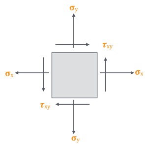
A typical 2D stress element is shown below with all indicated components shown in their positive sense:
The TOPIC of MOHR'S Circle can exist referenced under the SUBJECT of MECHANICS OF MATERIALS on page 81 of the NCEES Supplied Reference Handbook, Version 9.4 for Calculator Based Testing.
Using a graphical arroyo, we are able to determine the PRINCIPAL STRESSES on each aeroplane using a MOHR'South CIRCLE.
Mohr'due south circle is a geometric representation of the 2-D transformation of stresses, in which the component stresses and are found as the coordinates of a point whose location depends upon the bending to determine the attribute of the cross section.
The Mohr's circle is used to determine the principle angles (orientations) of the principal stresses without have to plug an angle into stress transformation equations.
To draw a Mohr'southward Circumvolve for a typical 2-D element, we tin use the following procedure to determine the master stresses.
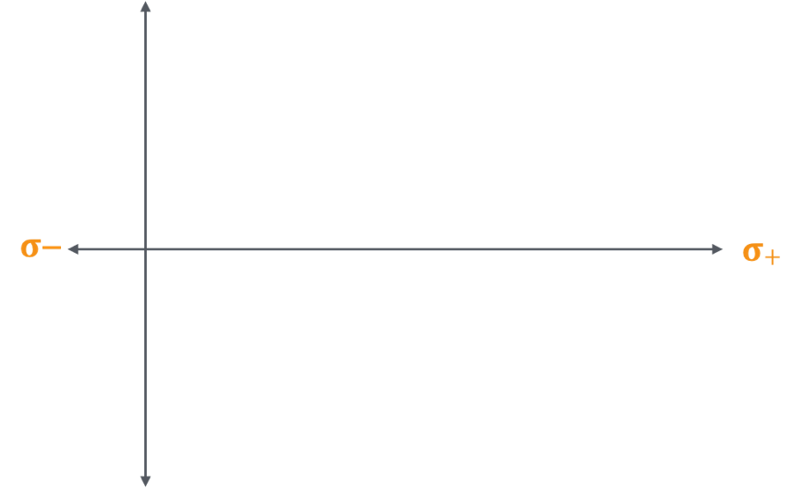
Define The Shear Stress Coordinate System:
1. Define the coordinate system for the normal and shear axes – Tensile normal stress components are plotted on the horizontal centrality and are considered positive. Compressive normal stress components are also plotted on the horizontal axis and are negative.
Define The Torsional Coordinate System:
two. For the structure of a Mohr's circumvolve, shearing stresses are plotted To a higher place the normal stress centrality when the pair of shearing stresses, acting on opposite and parallel faces of an element, form a CLOCKWISE (cw) couple. Shearing stresses are plotted Beneath the normal axis when the shear stresses grade a COUNTERCLOCKWISE (ccw) couple.

Plot The Shear Stress Values:
iii. Plot the shear stress values given in the problem statement, or plot generic points on the for σx-axis and σy as shown below.

Plot The Magnitude Of The Couple:
4. Plot the magnitude of the couple given in the problem argument with a clockwise (cw) couple existence plotted above the σx-axis, and a counterclockwise (ccw) couple existence plotted below the σx-axis.If not values are provided for the moment plot generic points above and below the σ-axis for τxy as shown below.

Obtain The Heart Of The Mohr'southward Circle:
5. The centre of the Mohr's circle is obtained graphically by plotting the two points representing the two known states of stress, and drawing a directly line between the two points. The intersection of this directly line and the -centrality is the location of the center of the circle.

Describe The Mohr'due south Circle:
6. Draw the Mohr'southward circle assuming the connection line equally the diameter of the circle, using the intersection of the diagonal straight line and the σ-centrality equally the centre of the circle.

Stress Analysis With The Mohr's Circle:
7. Stress Assay on Mohr's circumvolve – To get normal and shear stress values at any plane theta, have bending 2φ in the Mohr's circumvolve starting from diagonal of the circle and locate a peripheral bespeak as as shown. Shear stress value will be on the y-axis and normal stress values will be on the x-centrality.
Source: https://blog.prepineer.com/how-to-construct-a-mohrs-circle/
Enviar um comentário for "How to Draw Planar Tensile and Shear Stress"